I have received a few questions about the robot’s movements not always moving correctly like jumping or not rotating at the same speed and distance. To help understand the cause and effect, below are a series of diagrams and graphs to help explain.
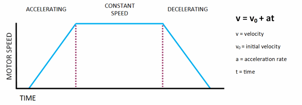
First the ideal motion for the robot’s motors is to accelerate, move a constant speed, then decelerate to a stop. Below is an image showing this motion. The logic controlling the motor’s velocity needs to calculate the velocity for any given time during the motion.
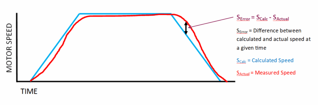
Below shows the calculated speed profile (blue) and the measured speed (red). Ideally these two lines overlap each. Or more likely would be very close to each other. The goal is to make the speed error (Serror) has small as possible throughout the motion.
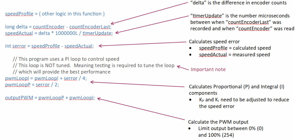
This is where a PID control logic can help make the speed error as small as possible. Below is a PID control block for velocity control that is modified to match more closely to a motor and encoder feedback. First PID states for Proportional-Integral-Derivative control. In the example below, we are only using the Proportional (P) and Integral (I) components. The Derivative (D) will be zero (0.00) for this application. Using just a PI loop is simpler to understand and adjust.

The diagram above is convert to code within the robot’s program. See the code below.
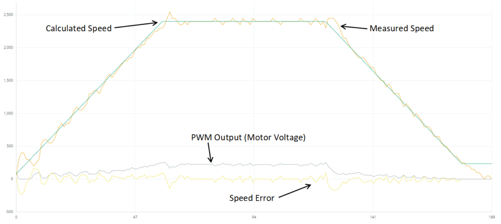
Determining the correct KP and KI values requires an accurate calculated velocity to compare against. The graph below shows the calculated speed value and distance value for a move.

Note: The graphs show on this page and the following are from the Arduino IDE Plotter tool. Which is a hint that you should be using this or a similar tool to determine if your robot’s movements are accurate.
The graph below shows the Calculated Speed and the Measured Speed. Notice the Measured Speed appears to keep varying. This is an effect of the very low encoder pulses produced during the time interval used to calculate the speed. In this case the speed is calculated every 1/50 of a second. A difference of one or two encoder pulses will be amplified by using a small time interval. To improve the measured speed accuracy, either a longer time interval is needed or an encoder with a higher pulses per revolution should be used. The time interval is a balancing act between a more accurate measured speed and being too slow to respond to errors.
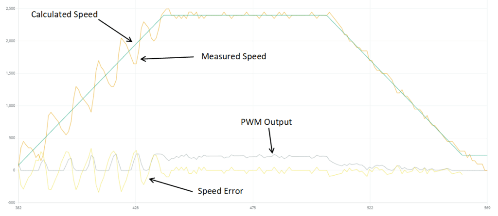
Determining a valid value for KP and KI requires try and error. The graph on the previous page shows a motor under good control. Can the performance be improved? Yes!!
Below is an example where the KI value was doubled. In the example below, this caused the system to be unstable and oscillate.
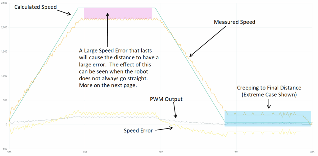
I have seen several comments on the Internet about using Proportional control only. This means the KI and KD values are zero. While this is easier to program, I do not recommend this approach. The Integral component will sum the speed error and help reduce the speed error. The example below shows the measured speed never reached the calculated speed. While the speed profile does not look too bad, remember the goal is for the encoder to travel a define number of encoder pulses or distance. In the example below, the motor was required to continue at a slow speed until the target distance was reached. This slow speed creep can be acceptable provided you can finish the track within the required track time. Otherwise this is lost time that could be used to reach additional gates.
Coordinated Motion
Most robots are using two motors to move around the track. This is called “coordinated motion” where both motors start and finish at the same time. Provided the speed is controlled accurately. Below are a series of diagrams that should help understand why the robot may not go straight or curve.
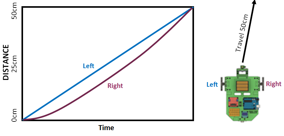
To travel in a straight line, both the left and right motor must move at the same speed at the same time and travel the same distance as shown below.

In the example below the right motor did not rotated slower at the start of the motion.
While both motors did rotate forward for 50cm, the robot curved to the right due to the right motor was behind the position of the left motor.
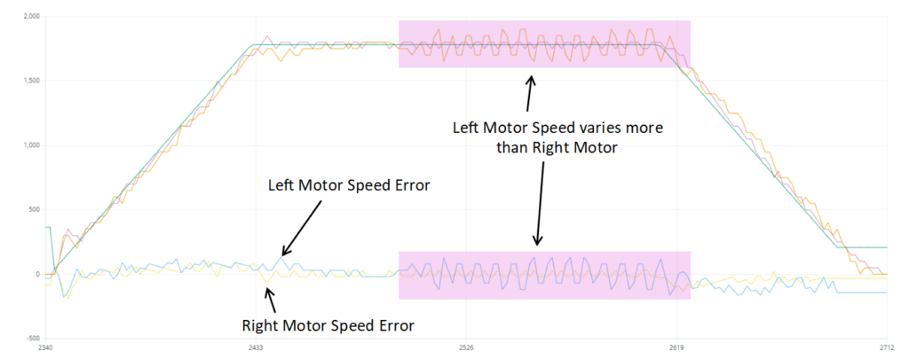
This is why graphing a motor’s motion is very important. You need to evaluate the entire motion for large speed errors. Do not look at the calculated speed or measured speed. Look at the speed error value for large differences. These could cause the robot to not move in a perfectly straight line.
Hope this helps.